Stepper motors are used for control of the temperature regulation, air distribution and recirculation doors on automatic HVAC systems.
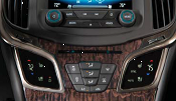
Vehicle occupants can select the desired position of the air temperature door, mode door and recirculation door, using the switches and dials on the HVAC controls.
Selected values are passed to the HVAC control module as serial data. The HVAC control module supplies a 12V control voltage to the stepper motor and energizes the four stepper motor coils with a pulsed ground signal. The stepper motor then moves the appropriate door into the calculated position in order to reach the selected position

Precise Stepper Motors
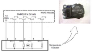
The new actuator, called a stepper motor, was first employed with the introduction of the GM Global architecture. The actuator is an externally driven or “dumb” actuator that provides more precise control with increased torque. The motor driver and position detection functions are located in the HVAC control module. The stepper motor is a bipolar design with four coil windings sharing a common 12V power feed.

5-wire stepper motor actuator
The null point of the stepper motor will be calibrated if the stepper motor is new. When the stepper motor is calibrated, the HVAC control module can drive the applicable coil to reach the exactly desired position of the door.
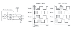
The stepper motor operates by sequentially changing the magnetic fields that surround the inner drive rotor. The rotor has permanent magnets with alternating fields embedded along its axis. To create movement, the HVAC control module grounds each of the four coils in a predetermined sequence. It is this sequence of magnetic fields that cause the rotor to move in either direction in stepped increments.

Stepper motor operation
Position is determined by the HVAC control module by counting pulses from the non-energized coils as the permanent magnets pass those coils. Previous actuators had 255 counts. The present ones can exceed 1000 counts.
The motor does not have physical stops; the physical stops are provided by the door within the housing. These stops are learned by the HVAC control module during calibration.
HVAC Diagnostics
Diagnostics can be run when the ignition is on and the HVAC control module is on.
DTC B023A 02 is set if the stepper motor supply output is shorted to ground.
DTC B0223 01, B022A 01, B0233 01, B023A 01, B0408 01 or B0418 01 is set if at least one control circuit of the appropriate stepper motor is shorted to voltage when the motor starts moving. Faults are not detected when the motor is already running or the target position is already reached.
DTC B0223 06, B022A 06, B0233 06, B0408 06 or B0418 06 is set if at least one control circuit of the appropriate stepper motor is shorted to ground or open when the motor starts moving. Faults are not detected when the motor is already running or the target position is already reached.
When DTC B023A is set, the affected output is switched off for hardware protection. All stepper motors are deactivated.
When DTC B0223, B022A, B0233, B0408 or B0418 is set, the affected output is switched off for hardware protection. Only the affected stepper motor is deactivated.
For more information about the latest HVAC technology and repairs, check out ACDelco training course S-AC07-03.01ILT, HVAC Control System Operation and Diagnostics[LG1] .
Contributor:
ACDelco Technical Assistance Centre
Questions? Please send us a note via our Contact Us.
If you’d like to speak to one of our TAC agents, call the ACDelco Info-Line.
Vehicle occupants can select the desired position of the air temperature door, mode door and recirculation door, using the switches and dials on the HVAC controls.
Selected values are passed to the HVAC control module as serial data. The HVAC control module supplies a 12V control voltage to the stepper motor and energizes the four stepper motor coils with a pulsed ground signal. The stepper motor then moves the appropriate door into the calculated position in order to reach the selected position
Precise Stepper Motors
The new actuator, called a stepper motor, was first employed with the introduction of the GM Global architecture. The actuator is an externally driven or “dumb” actuator that provides more precise control with increased torque. The motor driver and position detection functions are located in the HVAC control module. The stepper motor is a bipolar design with four coil windings sharing a common 12V power feed.
5-wire stepper motor actuator
The null point of the stepper motor will be calibrated if the stepper motor is new. When the stepper motor is calibrated, the HVAC control module can drive the applicable coil to reach the exactly desired position of the door.
The stepper motor operates by sequentially changing the magnetic fields that surround the inner drive rotor. The rotor has permanent magnets with alternating fields embedded along its axis. To create movement, the HVAC control module grounds each of the four coils in a predetermined sequence. It is this sequence of magnetic fields that cause the rotor to move in either direction in stepped increments.
Stepper motor operation
Position is determined by the HVAC control module by counting pulses from the non-energized coils as the permanent magnets pass those coils. Previous actuators had 255 counts. The present ones can exceed 1000 counts.
The motor does not have physical stops; the physical stops are provided by the door within the housing. These stops are learned by the HVAC control module during calibration.
HVAC Diagnostics
Diagnostics can be run when the ignition is on and the HVAC control module is on.
DTC B023A 02 is set if the stepper motor supply output is shorted to ground.
DTC B0223 01, B022A 01, B0233 01, B023A 01, B0408 01 or B0418 01 is set if at least one control circuit of the appropriate stepper motor is shorted to voltage when the motor starts moving. Faults are not detected when the motor is already running or the target position is already reached.
DTC B0223 06, B022A 06, B0233 06, B0408 06 or B0418 06 is set if at least one control circuit of the appropriate stepper motor is shorted to ground or open when the motor starts moving. Faults are not detected when the motor is already running or the target position is already reached.
When DTC B023A is set, the affected output is switched off for hardware protection. All stepper motors are deactivated.
When DTC B0223, B022A, B0233, B0408 or B0418 is set, the affected output is switched off for hardware protection. Only the affected stepper motor is deactivated.
For more information about the latest HVAC technology and repairs, check out ACDelco training course S-AC07-03.01ILT, HVAC Control System Operation and Diagnostics[LG1] .
Contributor:
ACDelco Technical Assistance Centre
Questions? Please send us a note via our Contact Us.
If you’d like to speak to one of our TAC agents, call the ACDelco Info-Line.